Friday, March 18, 2011

SERIAL PORTS AND COMMUNICATION


HELLO FRIENDS
Today i am going to discuss serial  ports and how they communicate or serial communication . i am writing about this technology due to one of
my friend,you want to know why? actually  few days back my friend
went for an interview and he was asked by interviewer that tell
me something about SERIAL AND PARALLEL PORT programming
He got confuse and start stammering .After an interview he gave me call
and start discussing the things. I also became curious after this and start
to search and read about it.

So lets start today's agenda what is serial port and how they communicate.Do not worry i will discuss parallel port in my next blog

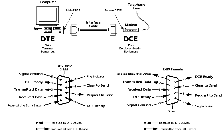
SERIAL COMMUNICATION AND SERIAL PORTS:

With a serial connection, information is sent across one wire, one data bit at a time. The 9-pin serial connector on most PCs uses two loops of wire, one in each direction, for data communication, plus additional wires to control the flow of information as you can see in the picture. In any given direction, data is still flowing over a single wire.


now i will give one more picture about pins details

there are only two pins(pin 1 and pin 2) are used for sending and receiving the bits or data.The rest of them are for data flow control.


Now discuss how the serial port communicate or serial communication.IN serial communication only one bit is send at a time.when first bit reach to destination then second start to travel

In serial communication basically there are two fundamental electrical lines one is for clock and other is for data.the actual data is transferred  BIT by BIT on data line.The clock line signals when a bit ends and other bit start.The clock line changes it level,that is when it goes HIGH from low or vice versa  ,signal this for transmission of next bit.

Do serial port need different cable for transmission? yes of course.they are known as serial cable.serial cable has two ends .one end of serial cable know as DTE (data terminal equipment) and other is known as DCE (data circuit-terminating equipment).


so my laptop port is DTE port and the cable connector also know as MALE .I  have give enough example to make the thing clarify.In my upcoming  blogs I  will discuss about parallel port..


SO COFFEE TIME !!
BYE  FOR NOW


Wednesday, March 16, 2011

DIFFERENCE BETWEEN HASHING AND ENCRYPTION


HELLO friends

When i first read about hashing and encryption i got little bit confused and was thinking "WHAT IS THE DIFFERENCE BETWEEN THEM". Actually I got introduce with these two terms when i was configuring my routers password specially when i was configuring ppp authentication.After that i decide to explore about these two stuffs


let start with brief analysis of both terms and how they are different with each other.

Hashing an encryption both of them are use to hide the original contents of data into some unrecognizable format. so it is clear that both of them  are use to protect the data from intruders.
                                                  

The basic difference is that ENCRYPTION is a reversible process while HASHING is a irreversible process.
Now i will discuss in details regarding algorithm of each one.

    
CASE 1 -HASHING

Basically, this hash algorithm is a formula used to convert a variable-length message into a fixed-length hash. It is also important to understand that this is a one-way function. A message can produce a hash, but a hash cannot produce the original message. After the hash is calculated, it is sent over the network together with the message. At the other end, the receiver performs the same action. It sends the message and the shared key through the hash algorithm and then compares the two hashes to verify whether they match.


imagepreshared.JPG    
image


Now i will tell you what is going on .As you can see that we have a plain text "JOHN" and we have to convert it into cipher text with hashing algorithm. suppose Y is our hashing table algorithm.It always convert plain text "john" into "XYZ" cipher text.Everytime cypher text will be "XYZ".

NOTE-Please pay attention here in third figure that cypher text "XYZ" is not going to convert into "JOHN"
plain text.so it is not easy or intruder to catch private data.

In the above figure(where routers are shown) it is application of hashing algorithm.

CASE 2 -ENCRYPTION.
Now it is time for encryption fundamentals.In encryption also plain text is converted into cypher text and it is reversible process.i will explain with the help of figure below
.
imageimage      

refer to above (left) figure ."JOHN" is our plain text and "X" is our encryption algorithm and what we found here every time algorithm"X" will produce different cypher text. As we can see from figure first time cipher text was"XYZ" and second time it is "ABC".so we can conclude that every time it will produce different cipher text unlike HASHING ALGORITHM.

refer to above (right) our cipher text "XYZ" is going to convert into plain text "JOHN" by using encryption algorithm "X".

ENCRYPTION has two class-

1> SYMMETRIC ENCRYPTION-less secure,both peer uses same key yo encrypt and decrypt the data  .      


  2> ASYMMETRIC   ENCRYPTION -more secure ,each peer uses different key to encrypt or decrypt the    
       data                                                             


HOPE THIS DOCUMENT WILL PROVE
USEFUL TO ALL TECH GEEKS.

now i am not anymore confused because i got the concept.


BYE FOR NOW.

Friday, March 11, 2011

DIFFERENT TYPE OF PROTOCOLS


Today i am going to discuss classification of ROUTING PROTOCOLS.
let me discuss different type/class of routing protocols
.
basically routing protocols is divided into two parts-
1> INTERIOR GATEWAY PROTOCOL
2> EXTERIOR GATEWAY PROTOCOL

now INTERIOR GATEWAY PROTOCOL is divided into two parts
1>DISTANCE VECTOR ROUTING PROTOCOLS
2>LINK STATE ROUTING PROTOCOLS

now DISTANCE VECTOR ROUTING PROTOCOLS is divided into 3 parts and i am also giving example of each one

1>CLASSFUL-- RIP and IGRP are example of classful routing protocols where IGRP is cisco proprietary

2>CLASSLESS--RIPV2 and EIGRP are example of classless routing protocols where EIGRP is cisco proprietary

3>1PV6-RIPng and EIGRP for IPV6 are example of IPV6 routong protocols.

now its time for LS routing protocols and again it is classified on same parameters that is classless,ipv6.but in this classification classfull is not present

1>CLASSLESS-OSPFv2 and IS-IS are example of classless routing protocols of link state

2>IPV6--OSPFv3 and IS-IS for IPV6 are example of IPV6 of link state routing protocols..

now its time for EXTERIOR GATEWAY PROTOCOLS PATH VECTOR,again classification on same parameters classful,classless,ipv6.let me give you example to make it more clear.


1>CLASSFUL-- EGP is an example of classful exterior gateway protocols path vector

2>CLASSLESS--BGPv4 is an example of classless exterior gateway protocols path vector

3>1PV6-BGPv4 FOR IPV6 is an example of ip version 6 exterior gateway protocols path vector

i am providing some images of diffrent protocols which will make you help to understand this stuff-


Friday, February 25, 2011

TCP: TRANSMISSION CONTROL PROTOCOL

hello guys-

today i am going to discus  TCP.very very very conceptual topic.

if you have good hands on tcp then you are hot cake in networking field.i will try to give a very good concept of tcp in this blog.

many question are assosciate with TCP like what is tcp.where tcp lies in network layer and so on?

TCP- transmission control protocol

this protocols  reside in transport layer(layer 4) of OSI model..do you know who else reside in network layer ?
it is UDP(use datagram protocol).it is also transport layer protocol

basic difference between TCP and UDP is reliable concerns, TCP more reliable and UDP less.

i will discuss UDP in my next blog.right now we  will discuss TCP.


Where and why would we use the TCP ?


TCP is used in almost every type of network. As a protocol, it is not restricted to any type of network topology, whether it be a local area network (LAN) or wide area network (WAN). Being a transport protocol, we call it a transport protocol because it's located in the transport layer of the OSI model its primary job is to get data from one location to another, regardless of the physical network and location.


and why we use TCP because it is more reliable than UDP(other network layer protocol)


The concept of a transport protocol-


TCP is a transport protocol and this means it is used to transfer data of other protocols.dont u think it sound weird? no it is not.


let me try to present an analogy of TCP.
just think tcp is like carriage or truck which is used to take the applicatoin layers protocol (HTTP,SMTP.POP,FTP) from source to destination.


the road on which our carriage travelling is layer 3 network layer. now let me try to summarize this analogy,

1> our carriage or truck(TCP)
2>our stuffs or goods present in truck(is upper layer protocols such as  HTTP.POP,FTP,SMTP).
3>our road or way from source to destination is network layer.


so now we can conclude that our stuffs(upper layer protocols) are safe and secure.


Some common protocols that use TCP are: FTP, Telnet, HTTP, HTTPS, DNS, SMTP and POP3. Let's have a closer look at the main characteristics of this wonderful protocol.


now i would like to discuss in details about TCP.


When people refer to "TCP/IP" remember that they are talking about a suite of protocols and not just one protocol, like most people think. TCP/IP is not one protocol.

Main Features-
       1> Reliable Transport
      2>Connection-Oriented
      3>Flow Control
      4>Windowing
      5>Acknowledgements
      6>More overhead

Reliable Transport
It's a reliable transport because of the different techniques it uses to ensure that the data received is error free. TCP is a robust protocol used for file transfers where data error is not an option. When you decide to download a 500MB file from a website, you wouldn't want to find out after the download is complete that the file has an error! Even though, in reality, this does happen, it just goes to show that you can't always be perfect with certain things.


this picture shows TCP header with in ethernet 2 frame.


The diagram below shows the individual breakdown of each field within the TCP header along with its length in bits.
Remember that 8 bits equal to 1 byte.
The most popular fields within the TCP header are the Source Port, Destination Port and Code bits. These Code bits are also known as 'flags'.
The rest of the fields help make sure all TCP segments make it to their destination and are reassembled in the correct order, while at the same time providing an error free mechanism should a few segments go missing and never reach their destination.


CONNECTION -ORIENTED-

What this basically means is that a connection is established between the two hosts or rather, the two computers, before any data is transferred. When the term "connection is established" is used, this means that both computers know about each other and have agreed on the exchange of data. This is also where the famous 3-way handshake happens. You will find the SYN and ACK bits in the Code bits field which are used to perform the 3-way handshake. Thanks to the 3-way handshake, TCP is connection oriented.
The following diagram explains the procedure of the 3-way handshake:
STEP 1: Host A sends the initial packet to Host B. This packet has the "SYN" bit enabled.Host B receives the packet and sees the "SYN" bit which has a value of "1" (in binary, this means ON) so it knows that Host A is trying to establish a connection with it.

STEP 2: Assuming Host B has enough resources, it sends a packet back to Host A and with the "SYN and ACK" bits enabled (1). The SYN that Host B sends, at this step, means 'I want to synchronise with you' and the ACK means 'I acknowledge your previous SYN request'.

STEP 3: So... after all that, Host A sends another packet to Host B and with the "ACK" bit set (1), it effectively tells Host B 'Yes, I acknowledge your previous request'.
Once the 3-way handshake is complete, the connection is established (virtual circuit) and the data transfer begins

FLOW CONTROL-

Flow control is used to control the data flow between the connection. If for any reason one of the two hosts are unable to keep up with the data transfer, it is able to send special signals to the other end, asking it to either stop or slow down so it can keep up.
For example, if Host B was a webserver from which people could download games, then obviously Host A is not going to be the only computer downloading from this webserver, soHost B must regulate the data flow to every computer downloading from it. This means it might turn to Host A and tell it to wait for a while until more resources are available because it has another 20 users trying to download at the same time.
Below is a diagram that illustrates a simple flow control session between two hosts. At this point, we only need to understand the concept of flow control:
Generally speaking, when a machine receives a flood of data too quickly for it to process, it stores it in a memory section called a buffer. This buffering action solves the problem only if the data bursts are small and don't last long.
However, if the data burst continues it will eventually exhaust the memory of the receiving end and that will result in the arriving data being discarded. So in this situation the receiving end will simply issue a "Not ready" or "Stop" indicator to the sender, or source of the flood. After the receiver processes the data it has in its memory, it sends out a "Ready" or "Go" transport indicator and the sending machine receives the "Go" indicator and resumes its transmission

WINDOWING

Data throughput, or transfer efficiency, would be low if the transmitting machine had to wait for an acknowledgment after sending each packet of data. Because there is time available after the sender transmits the data segment and before it finishes processing acknowledgments from the receiving machine, the sender uses the break to transmit more data. If we wanted to briefly define Windowing we could do so by stating that it is the number of data segments the transmitting machine is allowed to send without receiving an acknowledgment for them.
Windowing controls how much information is transferred from one end to the other. While some protocols quantify information by observing the number of packets, TCP/IP measures it by counting the number of bytes.
Let's explain what is happening in the above diagram.
Host B is sending data to Host A, using a window size equal to one. This means that Host B is expecting an "ACK" for each data segment it sends to Host A. Once the first data segment is sent, Host A receives it and sends an "ACK 2" to Host B. You might be wondering why "ACK 2"and not just "ACK"?
The "ACK 2" is translated by Host B to say: 'I acknowledge (ACK) the packet you just sent me and I am ready to receive the second (2) segment'. So Host B gets the second data segment ready and sends it off to Host A, expecting an "ACK 3" response from Host A so it can send the third data segment for which, as the picture shows, it receives the "ACK 3".
However, if it received an "ACK 2" again, this would mean something went wrong with the previous transmission and Host B will retransmit the lost segment. We will see how this works in the Acknowledgments section later on. Let's now try a different Window size to get a better understanding.. let's say 3!
Keep in mind the way the "ACK's" work, otherwise you might find the following example a bit confusing. If you can't understand it, read the previous example again where the Window size was equal to one.
In the above example, we have a window size equal to 3, which means that Host B can send 3 data segments to Host A before expecting an "ACK" back. Host B sends the first 3 segments (Send 1, Send 2 and Send 3), Host A receives them all in good condition and then sends the"ACK 4" to Host B. This means that Host A acknowledged the 3 data segments Host B sent and awaits the next data segments which, in this case, would be 4, 5 and 6

ACKNOWLEDGEMENT-

Reliable data delivery ensures the integrity of a stream of data sent from one machine to the other through a fully functional data link. This guarantees the data won't be duplicated or lost. The method that achieves this is known as positive acknowledgment with retransmission. This technique requires a receiving machine to communicate with the transmitting source by sending an acknowledgment message back to the sender when it receives data. The sender documents each segment it sends and waits for this acknowledgment before sending the next segment. When it sends a segment, the transmitting machine starts a timer and retransmits if it expires before an acknowledgment is returned from the receiving end.
This figure shows how the Acknowledgments work. If you examine the diagram closely you will see the window size of this transfer which is equal to 3. At first, Host B sends 3 data segments to Host A and they are received in perfect condition so, based on what we learned,Host A sends an "ACK 4" acknowledging the 3 data segments and requesting the next 3 data segments which will be 4, 5, 6. As a result, Host B sends data segments 4, 5, 6 but 5 gets lost somewhere along the way and Host A doesn't receive it so, after a bit of waiting, it realises that 5 got lost and sends an "ACK 5" to Host B, indicating that it would like data segment 5 retransmitted. Now you see why this method is called "positive acknowledgment with retransmission".
At this point Host B sends data segment 5 and waits for Host A to send an "ACK" so it can continue sending the rest of the data. Host A receives the 5th data segment and sends "ACK 7" which means 'I received the previous data segment, now please send me the next 3'. The next step is not shown on the diagram but it would be Host B sending data segments 7, 8 and 9


More Overhead

As you can see, there is quite a neat mechanism under the TCP hood that enables data to be transferred error free. All the features the protocol supports come at a price, and this is the overhead associated with TCP.
When we talk about overhead, we are referring to all the different fields contained within the TCP header and error checking that takes place to ensure no portion of the data is corrupt. While for most this is a fair trade off, some people simply can't spare the extra processing power, bandwidth and increased time the TCP transactions require, for this reason we have the alternative UDP protocol, which you can read about in the UDP protocol section.


Friday, February 18, 2011

OVERVIEW OF NAT


  ,--|192.168.1.1 (Computer A) |
L |  |-------------------------|
A |--|192.168.1.2 (Computer B) |
N |  '-------------------------'
  |  ,-------------------------,
  '--|192.168.1.100   (ROUTER) |
     '-------------------------'
  i have a  LAN with two computers and router. The LAN has its own private addressing scheme (Normally 192.168.1.x or similar) and each device connected to the LAN gets an IP from this range.


 As far as the internet is concerned I have a single 'outside' IP address (The one provided by your ISP).


 Since the router acts as a gateway between the 'inside' (your private LAN) and the outside.


Router sits between the 'inside' and the 'outside' and forms a kind of bridge over which data can pass.


if my  ISP gives you the address 11.22.33.44 then my  network will look something like the this..


      ,-------------------------,
   ,--|192.168.1.1 (Computer A) |
L  |  |-------------------------|
A  |--|192.168.1.2 (Computer B) |
N  |  '-------------------------'
   |  ,-------------------------,
   '--|192.168.1.100            |       inside
======|                (ROUTER) |================
   ,--|11.22.33.44              |       outside
   |  '-------------------------'
I  |
S  |
P \|/
   
The basics (Or 'how  machines currently surf from a single IP')


 Now, when I set each computer to use 192.168.1.100 as its 'gateway' in the TCP/IP settings dialogue I am telling them where to send any traffic which does not belong in the 192.168.1.x range.


 Therefore, when I  type www.google.co.uk into  web browser this is translated into googles IP address say... 62.62.62.62 which obviously is NOT a part of 192.168.1.x so it gets sent to your router. 

What happens next is magic .

Lets follow what happens when Machine A (192.168.1.1) opens a temporary outgoing port, say 1025 ... and tries to connect to 62.62.62.62:80 (One of googles many webservers) 

Machine A sends a packet whos header contains...
SOURCE = 192.168.1.1 :1025
DESTINATION = 62.62.62.62 :80

... to the gateway ( router) for passing to the outside world

Router receives the packet, examines this header and makes a note in its 'translation table' 

INSIDE IP       INSIDE PORT    OUTSIDE IP     OUTSIDE PORT
---------------------------------------------------------------
192.168.1.1     1025           62.62.62.62
Now, just as each computer has 65000+ ports,  router also has 65000+ ports. It looks to see if port 1025 is available and in this case we will assume it is. It decides to use ITS port 1025 to send  data and notes this fact in the translation table 

INSIDE IP       INSIDE PORT    OUTSIDE IP     OUTSIDE PORT
---------------------------------------------------------------
192.168.1.1     1025           62.62.62.62    1025
This entry simply means, computer 192.168.1.1 (inside) used its port 1025 to send data to the public (outside) address 62.62.62.62... And the router sent this data from its own port 1025 (The 'outside port) 

It then sends the data... but only after changing the IP header 

packet received from LAN:
SOURCE = 192.168.1.1 :1025
DESTINATION = 62.62.62.62 :80

Packet sent to ISP:
SOURCE = 11.22.33.44 :1025
DESTINATION = 62.62.62.62 :80
 

Notice that the destination is the same, but now the packets source is *ISP SUPPLIED* (or public) address. This is imortant since there may be billions of computers with the 'inside' IP 192.168.1.1 all over the world but there should only be one device with the unique public IP 11.22.33.44 ( router) ... and because of this, google knows unambiguously where to send the replies. 
Thats fine. But when  router receives a reply from google, how does it know which computer to send it to 

The IP header of the reply (google -> router) looks like this:
SOURCE = 62.62.62.62 :13948
DESTINATION = 11.22.33.44 :1025


Translated packet as placed on LAN:
SOURCE = 62.62.62.62 :13948
DESTINATION = 192.168.1.1 :1025

And the packet is thus recieved by Machine A 

DO  NOT YOU THINK ITS FANTASTIC

How collisions are resolved when two machines use same Destination_IP / Local_PORT 


If Machine B also tried to contact google using a temporary outbound port 1025, but the routers port 1025 is 'in use' (possibly because of that last transaction involving Machine A) the router simply chooses a different port number. Thus it not only changes the IP from 192.168.1.2 to 11.22.33.44 but also the PORT from 1025 to perhaps 1027. And makes another note in the translation table:


INSIDE IP       INSIDE PORT    OUTSIDE IP     OUTSIDE PORT
---------------------------------------------------------------
192.168.1.1     1025           62.62.62.62    1025
192.168.1.2     1025           62.62.62.62    1027


Both machines have used the same inside port (1025) to talk to the same outside address (google at 62.62.62.62) but these are passed to google from different ports (1025 and 1027) and so, when replies come back to these two router ports it allows the router to identify where they belong.


The translation table above will convert:
Incoming data from outside address 62.62.62.62 arriving at routers outside port *1025* will be redirected to Machine A's port 1025 

Meanwhile...

Incoming data from outside address 62.62.62.62 arriving at routers outside port *1027* will be redirected to Machine B's port 1025 

And thats why both  machines can access the internet simultaneously even though 'the internet' sees only one IP. Each individual communication is differentiated by dynamically assigned port numbers.

NAT